_

_
Workshop includes interactive development kit that will be assembled and coded during the workshop classes, a computer could also be provided for the duration of the classes if a student does not have access to a laptop computer.

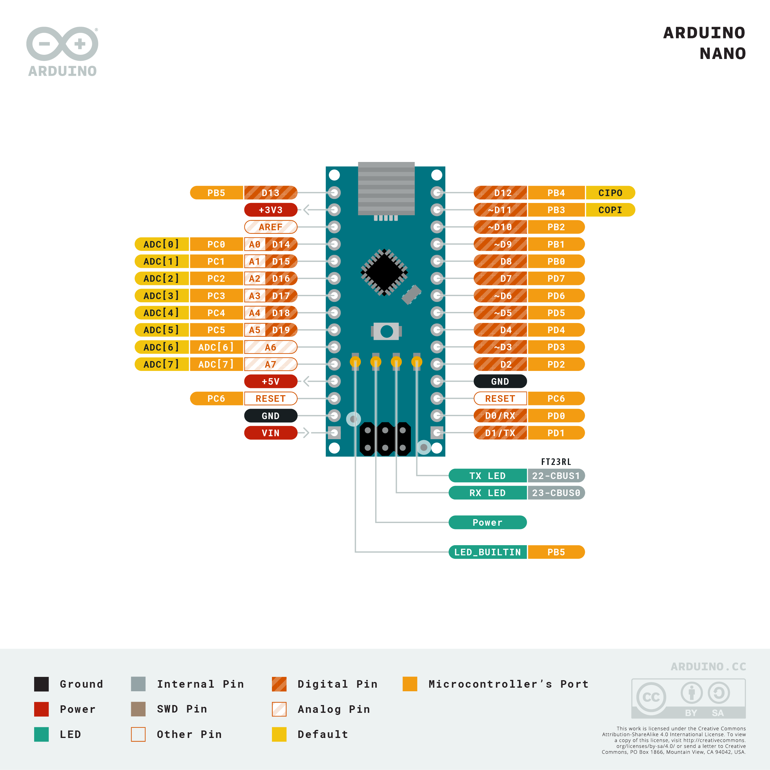
connect the Arduino to the computer with the USB cable
Copy the code below and paste it in the Arduino IDE
Select the board as "NANO" and upload the code
                          /*  sample code to make the LED blink  */

                          void setup() {
                          // initialize digital pin LED_BUILTIN as an output.
                          pinMode(LED_BUILTIN, OUTPUT);
                          }

                          void loop() {
                          digitalWrite(LED_BUILTIN, HIGH);   // turn the LED on (HIGH is the voltage level)
                          delay(1000);                       // wait for a second
                          digitalWrite(LED_BUILTIN, LOW);    // turn the LED off by making the voltage LOW
                          delay(1000);                       // wait for a second
                          }


connect the Arduino to the computer with the USB cable
Copy the code below and paste it in the Arduino IDE
Select the board as "NANO" and upload the code
                        void setup() {
                          Serial.begin(9600);
                            pinMode(13, OUTPUT);
                          }

                        void loop() {
                          // read the input on analog pin 0:
                          int sensorValue1 = analogRead(A3);
                          int sensorValue2 = analogRead(A5);
                          int sensorValue3 = analogRead(A4);
                          // Convert the analog reading (which goes from 0 - 1023) to a voltage (0 - 5V):
                          float voltage1 = sensorValue1 * (5.0 / 1023.0);
                          float voltage2 = sensorValue2 * (5.0 / 1023.0);
                          float voltage3 = sensorValue3 * (5.0 / 1023.0);

                          if (voltage3 < 4.5) {
                          digitalWrite(13, HIGH);   // turn the LED on (HIGH is the voltage level)
                          delay(50);              // wait for a second
                          digitalWrite(13, LOW);    // turn the LED off by making the voltage LOW
                          delay(50);
                          }

                            else if ((voltage1 > 0.05) && (voltage1 < 1.0)){
                            digitalWrite(13, HIGH);
                            delay(25);              // wait for a second
                            digitalWrite(13, LOW);    // turn the LED off by making the voltage LOW
                            delay(25);
                          }

                                else if ((voltage1 < 4.9) && (voltage1 > 4.0)) {
                            digitalWrite(13, HIGH);
                            delay(25);              // wait for a second
                            digitalWrite(13, LOW);    // turn the LED off by making the voltage LOW
                            delay(25);
                          }

                           else if ((voltage1 < 4.0) && (voltage1 > 2.55)) {
                            digitalWrite(13, HIGH);
                            delay(50);              // wait for a second
                            digitalWrite(13, LOW);    // turn the LED off by making the voltage LOW
                            delay(50);
                          }

                            else if ((voltage1 > 1.0) && (voltage1 < 2.45)){
                            digitalWrite(13, HIGH);
                            delay(50);              // wait for a second
                            digitalWrite(13, LOW);    // turn the LED off by making the voltage LOW
                            delay(50);
                          }
                            else if (voltage1 < 0.1){
                            digitalWrite(13,HIGH);
                          }
                            else if (voltage1 > 4.9) {
                            digitalWrite(13, HIGH);
                          }
                              else if (voltage2 > 4.9) {
                            digitalWrite(13, HIGH);
                          }

                            else if ((voltage2 < 4.9) && (voltage2 > 4.0)) {
                            digitalWrite(13, HIGH);
                            delay(25);              // wait for a second
                            digitalWrite(13, LOW);    // turn the LED off by making the voltage LOW
                            delay(25);
                          }

                            else if ((voltage2 < 4.0) && (voltage2 > 2.55)) {
                            digitalWrite(13, HIGH);
                            delay(50);              // wait for a second
                            digitalWrite(13, LOW);    // turn the LED off by making the voltage LOW
                            delay(50);
                          }
                            else if ((voltage2 > 1.0) && (voltage2 < 2.45)){
                            digitalWrite(13, HIGH);
                            delay(50);              // wait for a second
                            digitalWrite(13, LOW);    // turn the LED off by making the voltage LOW
                            delay(50);
                          }

                           else if ((voltage2 > 0.05) && (voltage2 < 1.0)){
                            digitalWrite(13, HIGH);
                            delay(25);              // wait for a second
                            digitalWrite(13, LOW);    // turn the LED off by making the voltage LOW
                            delay(25);
                          }
                            else if (voltage2 < 0.05){
                            digitalWrite(13,HIGH);
                          }

                          else {
                            digitalWrite(13,LOW);
                          }

                          // print out the value you read:
                            Serial.print(voltage1);
                            Serial.print(" ");
                            Serial.print(voltage2);
                            Serial.print(" ");
                            Serial.println(voltage3);
                        }


connect the Arduino to the computer with the USB cable
Copy the code below and paste it in the Arduino IDE
Select the board as "NANO" and upload the code
                            #include
                            /*
                            Controlling a servo position using a potentiometer (variable resistor)
                            by Michal Rinott

                            modified on 8 Nov 2013
                            by Scott Fitzgerald
                            http://www.arduino.cc/en/Tutorial/Knob
                           */

                           #include

                           Servo myservo;  // create servo object to control a servo

                           int potpin = 0;  // analog pin used to connect the potentiometer
                           int val;    // variable to read the value from the analog pin

                           void setup() {
                             myservo.attach(9);  // attaches the servo on pin 9 to the servo object
                           }

                           void loop() {
                             val = analogRead(potpin);            // reads the value of the potentiometer (value between 0 and 1023)
                             val = map(val, 0, 1023, 0, 180);     // scale it to use it with the servo (value between 0 and 180)
                             myservo.write(val);                  // sets the servo position according to the scaled value
                             delay(15);                           // waits for the servo to get there
                           }
connect the Arduino to the computer with the USB cable
Copy the code below and paste it in the Arduino IDE
Select the board as "NANO" and upload the code
#include
                            #ifdef __AVR__
                              #include
                            #endif

                            #define PIN 6

                            // Parameter 1 = number of pixels in strip
                            // Parameter 2 = Arduino pin number (most are valid)
                            // Parameter 3 = pixel type flags, add together as needed:
                            //   NEO_KHZ800  800 KHz bitstream (most NeoPixel products w/WS2812 LEDs)
                            //   NEO_KHZ400  400 KHz (classic 'v1' (not v2) FLORA pixels, WS2811 drivers)
                            //   NEO_GRB     Pixels are wired for GRB bitstream (most NeoPixel products)
                            //   NEO_RGB     Pixels are wired for RGB bitstream (v1 FLORA pixels, not v2)
                            //   NEO_RGBW    Pixels are wired for RGBW bitstream (NeoPixel RGBW products)
                            Adafruit_NeoPixel strip = Adafruit_NeoPixel(60, PIN, NEO_GRB + NEO_KHZ800);

                            // IMPORTANT: To reduce NeoPixel burnout risk, add 1000 uF capacitor across
                            // pixel power leads, add 300 - 500 Ohm resistor on first pixel's data input
                            // and minimize distance between Arduino and first pixel.  Avoid connecting
                            // on a live circuit...if you must, connect GND first.

                            void setup() {
                              // This is for Trinket 5V 16MHz, you can remove these three lines if you are not using a Trinket
                              #if defined (__AVR_ATtiny85__)
                                if (F_CPU == 16000000) clock_prescale_set(clock_div_1);
                              #endif
                              // End of trinket special code

                              strip.begin();
                              strip.setBrightness(50);
                              strip.show(); // Initialize all pixels to 'off'
                            }

                            void loop() {
                              // Some example procedures showing how to display to the pixels:
                              colorWipe(strip.Color(255, 0, 0), 50); // Red
                              colorWipe(strip.Color(0, 255, 0), 50); // Green
                              colorWipe(strip.Color(0, 0, 255), 50); // Blue
                            //colorWipe(strip.Color(0, 0, 0, 255), 50); // White RGBW
                              // Send a theater pixel chase in...
                              theaterChase(strip.Color(127, 127, 127), 50); // White
                              theaterChase(strip.Color(127, 0, 0), 50); // Red
                              theaterChase(strip.Color(0, 0, 127), 50); // Blue

                              rainbow(20);
                              rainbowCycle(20);
                              theaterChaseRainbow(50);
                            }

                            // Fill the dots one after the other with a color
                            void colorWipe(uint32_t c, uint8_t wait) {
                              for(uint16_t i=0; i < strip.numPixels(); i++) {
                                strip.setPixelColor(i, c);
                                strip.show();
                                delay(wait);
                              }
                            }

                            void rainbow(uint8_t wait) {
                              uint16_t i, j;

                              for(j=0; j < 256; j++) {
                                for(i=0; i < strip.numPixels(); i++) {
                                  strip.setPixelColor(i, Wheel((i+j) & 255));
                                }
                                strip.show();
                                delay(wait);
                              }
                            }

                            // Slightly different, this makes the rainbow equally distributed throughout
                            void rainbowCycle(uint8_t wait) {
                              uint16_t i, j;

                              for(j=0; j < 256*5; j++) { // 5 cycles of all colors on wheel
                                for(i=0; i< strip.numPixels(); i++) {
                                  strip.setPixelColor(i, Wheel(((i * 256 / strip.numPixels()) + j) & 255));
                                }
                                strip.show();
                                delay(wait);
                              }
                            }

                            //Theatre-style crawling lights.
                            void theaterChase(uint32_t c, uint8_t wait) {
                              for (int j=0; j < 10; j++) {  //do 10 cycles of chasing
                                for (int q=0; q < 3; q++) {
                                  for (uint16_t i=0; i < strip.numPixels(); i=i+3) {
                                    strip.setPixelColor(i+q, c);    //turn every third pixel on
                                  }
                                  strip.show();

                                  delay(wait);

                                  for (uint16_t i=0; i < strip.numPixels(); i=i+3) {
                                    strip.setPixelColor(i+q, 0);        //turn every third pixel off
                                  }
                                }
                              }
                            }

                            //Theatre-style crawling lights with rainbow effect
                            void theaterChaseRainbow(uint8_t wait) {
                              for (int j=0; j < 256; j++) {     // cycle all 256 colors in the wheel
                                for (int q=0; q < 3; q++) {
                                  for (uint16_t i=0; i < strip.numPixels(); i=i+3) {
                                    strip.setPixelColor(i+q, Wheel( (i+j) % 255));    //turn every third pixel on
                                  }
                                  strip.show();

                                  delay(wait);

                                  for (uint16_t i=0; i < strip.numPixels(); i=i+3) {
                                    strip.setPixelColor(i+q, 0);        //turn every third pixel off
                                  }
                                }
                              }
                            }

                            // Input a value 0 to 255 to get a color value.
                            // The colours are a transition r - g - b - back to r.
                            uint32_t Wheel(byte WheelPos) {
                              WheelPos = 255 - WheelPos;
                              if(WheelPos < 85) {
                                return strip.Color(255 - WheelPos * 3, 0, WheelPos * 3);
                              }
                              if(WheelPos < 170) {
                                WheelPos -= 85;
                                return strip.Color(0, WheelPos * 3, 255 - WheelPos * 3);
                              }
                              WheelPos -= 170;
                              return strip.Color(WheelPos * 3, 255 - WheelPos * 3, 0);
                            }


connect the Arduino to the computer with the USB cable
Copy the code below and paste it in the Arduino IDE
Select the board as "NANO" and upload the code
                        // the setup function runs once when you press reset or power the board
                        void setup() {
                          // initialize digital pin LED_BUILTIN as an output.
                          pinMode(LED_BUILTIN, OUTPUT);
                        }

                        // the loop function runs over and over again forever
                        void loop() {
                          digitalWrite(LED_BUILTIN, HIGH);   // turn the LED on (HIGH is the voltage level)
                          delay(1000);                       // wait for a second
                          digitalWrite(LED_BUILTIN, LOW);    // turn the LED off by making the voltage LOW
                          delay(1000);                       // wait for a second
                        }

connect the Arduino to the computer with the USB cable
Copy the code below and paste it in the Arduino IDE
Select the board as "NANO" and upload the code
                    // constants won't change. They're used here to set pin numbers:
                    const int buttonPin = 2;     // the number of the pushbutton pin
                    const int ledPin =  13;      // the number of the LED pin

                    // variables will change:
                    int buttonState = 0;         // variable for reading the pushbutton status

                    void setup() {
                      // initialize the LED pin as an output:
                      pinMode(ledPin, OUTPUT);
                      // initialize the pushbutton pin as an input:
                      pinMode(buttonPin, INPUT);
                    }

                    void loop() {
                      // read the state of the pushbutton value:
                      buttonState = digitalRead(buttonPin);

                      // check if the pushbutton is pressed. If it is, the buttonState is HIGH:
                      if (buttonState == HIGH) {
                        // turn LED on:
                        digitalWrite(ledPin, HIGH);
                      } else {
                        // turn LED off:
                        digitalWrite(ledPin, LOW);
                      }
                    }


connect the Arduino to the computer with the USB cable
Copy the code below and paste it in the Arduino IDE
Select the board as "NANO" and upload the code
#include
                        #include

                        const int A01_PIN = A0; // X-axis analog input pin
                        const int A02_PIN = A1; // Y-axis analog input pin
                        const int A03_PIN = A2; // Photoresistor analog input pin
                        const int D01_PIN = 2; // Digital output pin for laser diode
                        const int D02_PIN = 3; // Digital output pin for neopixel wheel
                        const int D03_PIN = 4; // Button input pin

                        const int NUM_LEDS = 8; // Number of LEDs in the neopixel wheel
                        const int LED_COLORS[][3] = {
                          {255, 0, 0},    // Red
                          {255, 128, 0},  // Orange
                          {255, 255, 0},  // Yellow
                          {0, 255, 0},    // Green
                          {0, 255, 255},  // Cyan
                          {0, 0, 255},    // Blue
                          {128, 0, 255},  // Purple
                          {255, 0, 255}   // Magenta
                        };

                        Adafruit_NeoPixel pixels(NUM_LEDS, D02_PIN, NEO_GRB + NEO_KHZ800);
                        Servo xServo; // X-axis servo
                        Servo yServo; // Y-axis servo

                        int currentLed = 0; // Current LED position on the neopixel wheel
                        bool laserOn = false; // Flag to indicate if laser diode is on

                        void setup() {
                          pinMode(D01_PIN, OUTPUT); // Configure D01_PIN as output
                          pinMode(D03_PIN, INPUT_PULLUP); // Configure D03_PIN as input with internal pull-up resistor
                          pixels.begin(); // Initialize neopixel wheel
                          pixels.setBrightness(50); // Set the brightness of the neopixel wheel (adjust as needed)
                          xServo.attach(5); // Attach X-axis servo to pin 5
                          yServo.attach(6); // Attach Y-axis servo to pin 6
                        }

                        void loop() {
                          // Read analog inputs
                          int xValue = analogRead(A01_PIN);
                          int yValue = analogRead(A02_PIN);
                          int photoresistorValue = analogRead(A03_PIN);

                          // Map analog values to servo positions
                          int xServoPosition = map(xValue, 0, 1023, 0, 180);
                          int yServoPosition = map(yValue, 0, 1023, 0, 180);

                          // Control the servos
                          xServo.write(xServoPosition);
                          yServo.write(yServoPosition);

                          // Toggle laser diode state when button is pressed
                          if (digitalRead(D03_PIN) == LOW) {
                            if (!laserOn) {
                              laserOn = true;
                              digitalWrite(D01_PIN, HIGH); // Turn on the laser diode
                            } else {
                              laserOn = false;
                              digitalWrite(D01_PIN, LOW); // Turn off the laser diode
                              currentLed = (currentLed + 1) % NUM_LEDS; // Shift to the next LED position
                            }
                          }

                          // Map photoresistor value to LED color
                          int ledColorIndex = map(photoresistorValue, 0, 1023, 0, 3);

                          // Control the neopixel wheel
                          for (int i = 0; i < NUM_LEDS; i++) {
                            if (i == currentLed) {
                              pixels.setPixelColor(i, pixels.Color(LED_COLORS[ledColorIndex][0], LED_COLORS[ledColorIndex][1], LED_COLORS[ledColorIndex][2]));
                            } else {
                              pixels.setPixelColor(i, pixels.Color(0, 0, 0)); // Turn off other LEDs
                            }
                          }
                          pixels.show(); // Update the neopixel wheel

                          // Print the values of the analog inputs
                          Serial.print("X-axis value: ");
                          Serial.print(xValue);
                          Serial.print("\tY-axis value: ");
                          Serial.print(yValue);
                          Serial.print("\tPhotoresistor value: ");
                          Serial.print(photoresistorValue);
                          Serial.print("\tLED Color Index: ");
                          Serial.print(ledColorIndex);
                          Serial.print("\tX-axis Servo Position: ");
                          Serial.print(xServoPosition);
                          Serial.print("\tY-axis Servo Position: ");
                          Serial.println(yServoPosition);

                          delay(100); // Adjust the delay according to your needs
                        }
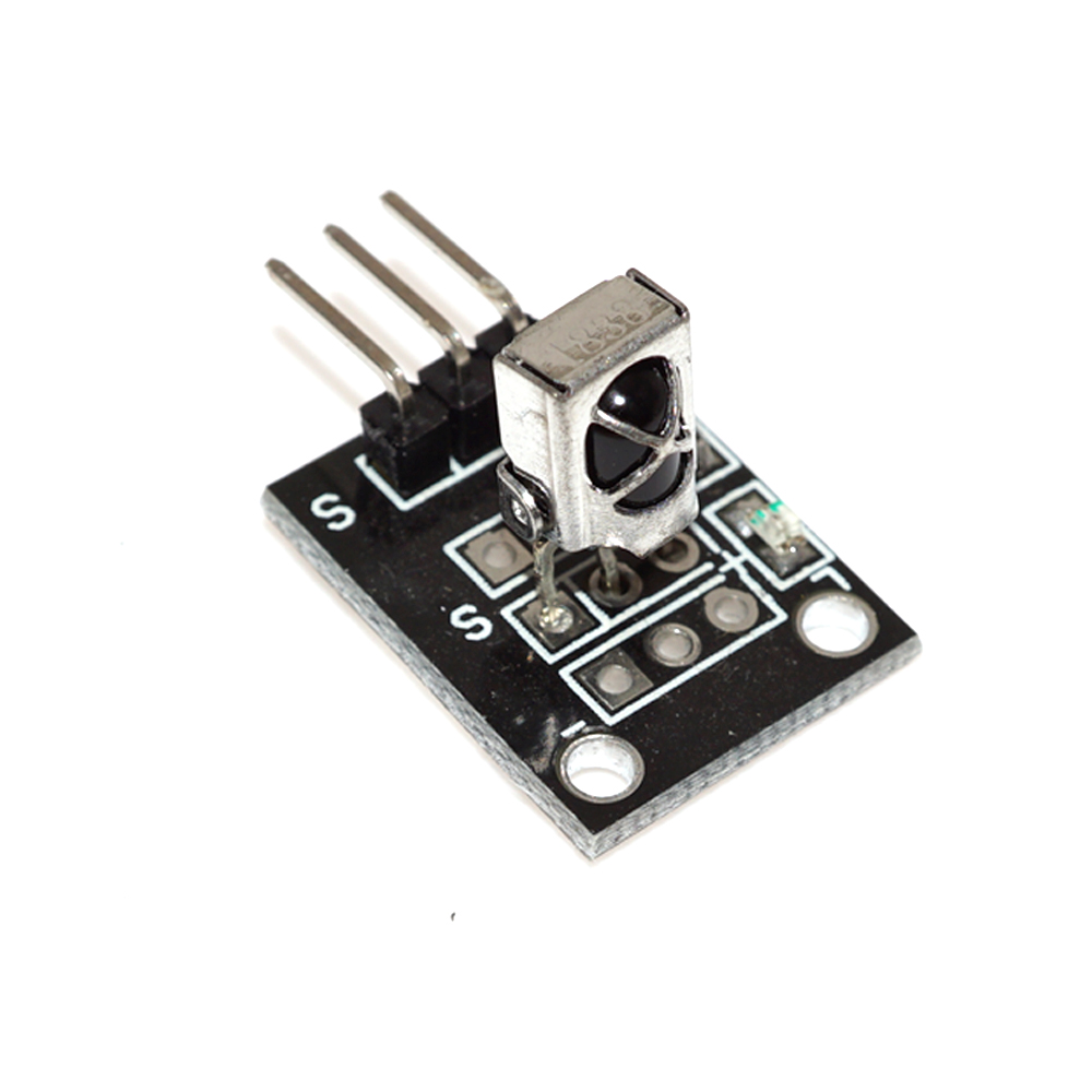
WORKSHOP DETAILS: The above images represent workshop kit that is included in the classes, click on each image for wiring information and code snippet
Date: 26 August and 2 September 2023
Time: 9:00 - 12:30 AM
Place: 26 Geelhoutkruin Arboretum Richards Bay
Single Price: R1200 (consists of 2 workshop classes and 1 DEV kit)
Pair price: R1500 (consists of 2 classes for 2 students and 1 DEV kit to share)
Explore new possiblities and learn using YOUR imaginantion and curiousosity. These workshops could inspire future projects and ideas that you might want to bring to life.


Join weekend workshops and learn all about building and programming electronic devices. Learn the Basics like blinking a LED up to building your own moving robots. ANYONE CAN DO IT. even the whole family.